Saturday, 14 December 2013

Tan delta ,Resistivity measurement of transformer oil

Insulating oil in an electrical power transformer is commonly known as Transformer Oil. It is normally obtained by fractional distillation and subsequent treatment of crude petroleum. That is why this oil is also known as Mineral Insulating Oil. Transformer Oil serves mainly two purposes one it is liquid insulation in electrical power transformer and two it dissipates heat of the transformer i.e. acts as coolant. In addition to these, this oil serves other two purposes, it helps to preserve the core and winding as these are fully immersed inside oil and another important purpose of this oil is, it prevents direct contact of atmospheric oxygen with cellulose made paper insulation of windings, which is susceptible to oxidation.

1. Electrical Parameters – Dielectric Strength , Specific Resistance, Dielectric Dissipation Factor.

2. Chemical Parameter - Water Content, Acidity, Sludge Content.
3. Physical Parameters - Inter Facial Tension, Viscosity, Flash Point, Pour Point.

Dielectric Strength of Transformer Oil

test kit for measuring breakdown voltage of transformer oil
Dielectric Strength of Transformer Oil is also known as Breakdown Voltage of transformer oil or BDV of transformer oil. Break down voltage is measured by observing at what voltage, sparking strants between two electrods immerged in the oil, separated by specific gap. low value of BDV indicates presence of moisture content and conducting substances in the oil. For measuring BDV of transformer oil, portable BDV measuring kit is generally available at site. In this kit, oil is kept in a pot in which one pair of electrodes are fixed with a gap of 2.5 mm (in some kit it 4mm) between them.

Specific Resistance ( Resistivity ) of Transformer Oil

This is another important property of transformer oil. This is measure of DC resistance between two opposite sides of one cm3 block of oil. Its unit is taken as ohm-cm at specific temperature. With increase in temperature the resistivity of oil decreases rapidly. Just after charging a transformer after long shut down, the temperature of the oil will be at ambient temperature and during full load the temperature will be very high and may go up to 90oC at over load condition. So resistivity of the insulating oil must be high at room temperature and also it should have good value at high temperature as well.
That is why specific resistance or resistivity of transformer oil should be measured at 27oC as well as 90oC.

Transformer winding resistance measurement

Transformer winding resistance measurement is carried out to calculate the I2R losses and to calculate winding temperature at the end of a temperature rise test. It is carried out as a type test as well as routine test. It is also done at site to ensure healthiness of a transformer that is to check loose connections, broken strands of conductor, high contact resistance in tap changers, high voltage leads and bushings etc.
There are different methods for measuring of transformer winding, likewise
♣ Current voltage method of measurement of winding resistance.
♣ Bridge method of measurement of winding resistance.
♠ Kelvin bridge method of Measuring Winding Resistance.
Transformer winding resistance measurement is carried out as a type test, routine test and also as a field test.
In the factory, it helps in determining the following :
(a) Calculation of the I2R losses in transformer

(b) Calculation of winding temperature at the end of temperature rise test of transformer.


(c) As a benchmark for assessing possible damages in the field.

Current Voltage Method of measurement of winding resistance

The transformer winding resistances can be measured by current voltage method. In this method of measurement of winding resistance, the test current is injected to the winding and corresponding voltage drop across the winding is measured.
By applying simple Ohm's law i.e. Rx = V ⁄ I, one can easily determine the value of resistance.
current voltage method of measurement of star winding resistancecurrent voltage method of measurement of delta winding resistance

Dielectric Dissipation Fact

Bridge Method of measurement of winding resistance

kelvin double bridge
The main principle of bridge method is based on comparing an unknown resistance with a known resistance.

When electric currents flowing through the arms of bridge circuit become balanced, the reading of galvanometer shows zero deflection that means at balanced condition no electric current will flow through the galvanometer. Very small value of resistance ( in milli - ohms range) can be accurately measured by Kelvin Bridge method whereas for higher value Wheatstone bridge method of resistance measurement is applied. In bridge method of measurement of winding resistance, the errors is minimized.

wheatstone bridgekelvin bridge

 Loss factor or  tan delta of Transformer oil

Dielectric Dissipation Factor is also known as loss factor or tan delta of transformer oil. When a insulating materials is placed between live part and grounded part of an electrical equipment, leakage current will flow. As insulating material is dielectric in nature the electric currentthrough the insulation ideally leads the voltage by 90o. Here voltage means the instantaneous voltage between live part and ground of the equipment. But in reality no insulating materials are perfect dielectric in nature. Hence electric current through the insulator will lead the voltage with an angle little bit shorter than 90o. Tangent of the angle by which it is short of 90o is called Dielectric Dissipation Factor or simplytan delta of transformer oil.
More clearly, the leakage current through an insulation does have two component one is capacitive or reactive and other one is resistive or active.
Again it is clear from above diagram, value of ′δ′ which is also known as loss angle,
tan delta of transformer oil
is smaller, means resistive component of the current IR is smaller which indicates high resistive property of the insulating material. High resistive insulation is good insulator. Hence it is desirable to have loss angle as small as possible. So we should try to keep the value of tanδ as small as possible. High value of this tanδ is an indication of presence of contaminants in transformer oil.
Hence there is a clear relationship between tanδ and resistivity of insulating oil. If resistivity of the insulating oil is decreased, the value of tan-delta increases and vice verse. So both resistivity test and tan delta test of transformer oil are not normally required for same piece of insulator or insulating oil.

In one sentence it can be said that, tanδ is measure of imperfection of dielectric nature of insulation materials like oil.

SWITCHING OVERVOLTAGES

™ There is a great variety of events that would initiate a switching surge in a power network.
™ The switching operations of greatest relevance to insulation design can be classified as follows:
1. Energization of transmission lines and cables. The following specific switching operations are some of the most common in this category:
a. Energization of a line that is open circuited at the far end
b. Energization of a line that is terminated by an unloaded transformer
c. Energization of a line through the low-voltage side of a transformer
2. Reenergization of a line. This means the energization of transmission line carrying charges trapped by previous line interruptions when high-speed reclosures are used. 
3. Load rejection. This is affected by a circuit breaker opening at the far end of the line. 
This may also be followed by opening the line at the sending end in what is called a line dropping operation. 
4. Switching on and off of equipment. All switching operations involving an element of the transmission network will produce a switching surge. 
a. Switching of high-voltage reactors 
b. Switching of transformers that are loaded by a reactor on their tertiary winding 
c. Switching of a transformer at no load 
5. Fault initiation and clearing. 

Some important switching operations which can lead to switching over-voltages

1-Line energization
2-Reclosing (energization of a line with trapped charges)
3-low voltage side Energization of a line
4- Energization a line terminated by an unloaded transformer
5- Load rejection at the receiving end of a line
6- Load rejection at the receiving end of a line followed by line dropping at the sending end
7- Interrupting lines at no-load (line dropping)
8- Switching of transformers at no-load
9- Switching reactor loaded transformers
10- Switching high voltage reactors
11- Switching at intermediate substations
12- Initiation of a single-phase to earth fault without a switching operation


Lightning over-voltages

Lightning Phenomenon 

 The lightning is a natural phenomenon generated during thunderstorm by electrostatic
discharge which produced electromagnetic radiations. The lightning is occasionally associated
with thunder due to the electric current passing through the lightning channel.

Types of Lightning
 Lightning discharges can be classified into three main types:
1. Intracloud discharge,
2. Cloud-to-cloud discharge and
3. Cloud-to-ground discharge.
 From the power system point of view, cloud-to-ground discharge is the frequent type that

generates lightning over-voltages on overhead distribution lines.

Lightning Process

 Figure 1.1 shows induced charges on transmission line when the thunder cloud located above
the transmission line. In Figure 1.1.a, the distribution of negative and positive charges of the
charged thunder cloud is depicted with different temperature values. In the base of the thunder
cloud, the negative charges center is at temperature -5 οC and located in the lower part of the
cloud. At higher elevation, there is a positive charging center with temperature less than -20 οC.
In the circumstances of many neighbor storm clouds, there are generated positive charges in a
small region at the cloud base as depicted in Figure 1.1.a . This small region temperature is
around 0 οC.


Figure 1.1.b shows the induced charge in the line through the down coming leader charge. 
These induced charges travel along the line with approximately the light velocity when the 
cloud is discharged. Otherwise, the induced charges remain at their positions without any 
traveling. The travelling of the induced charges along the line generates voltage surge in both 
sides of the line. This voltage is dependent on the lightning stroke location where it can be 
evaluated using the form: 

where E is the peak value of the voltage waves on the line, C1 is the capacitance between 
the cloud and the line, C2 is the capacitance between the line and the ground, q is the bound 
charge per unit length of the line, C is the capacitance per unit length of the line. 

 The induced overvoltage process can be simply interpreted considering principles of 
electrostatic induction and electromagnetic induction . 

Saturday, 7 December 2013

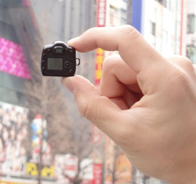
smallest camera

smallest camera

SEMINAR TOPICS –B.TECH (FINALYEAR EEE)

SEMINAR TOPICS –B.TECH (FINALYEAR EEE)

1. Hybrid Electric Vehicle
2. Hy-Wire
3. Illumination with Solid State lighting
4. Intelligent Management of Electrical Systems in Industries
5. Isoloop Magnetic Couplers
6. Large Scale Power Generation Using Fuel Cell
7. Local Multipoint Distribution Service
8. Low - k DielectricsS
9. Mesh Radio
10. MicroGrid
11. Nuclear Batteries
12. Optical Interconnects
13. Optical Technology in Current Measurement
14. PEA Space Charge Measurement System
15. Pebble-Bed Reactor
16. Polyfuse
17. Power Quality
18. Robotic control Using Fuzzy Logic
19. Robotic Monitoring of Power Systems
20. Snake Robot
21. Surge current protection using superconductors
22. Robotic Monitoring of Power Systems
23. Adaptive optics
24. Circuit Breaker Maintenance by Mobile Agent Software Technology
25. Digital Testing of High Voltage Circuit Breaker
26. Eddy current brakes
27. Electric Power line networking for a Smart Home
28. Electrical Impedance Tomography
29. Electro Dynamic Tether
30. Flexible Ship Electric Power System Design
31. Power System Contingencies
32. HVAC system
33. Process Automation Techniques
34. Adaptive Piezoelectric energy harvesting circuit
35. Lightning Protection Zones

36. Modern Surge Arresters
37. BiCMOS Technology
38. Electric Utility Industry.
39. End-Use Energy Efficiency Potential
40. Lightning Protection Using LFA-M
41. Aluminum Alloy Conductors
42. Hal Bach array
43. Surge current protection using superconductors
44. Magnetic Levitation
45. Fast quasi-static capacitance extraction using Csurf
46. Electrical and chemical diagnostics of transformer insulation
47. Micro Batteries
48. Magnet less Motors
49. Seasonal Influence on Safety of Substation Grounding
50. EL Lightning
51. Piezoelectric Actuators
52. Microprocessor Based Alternator Synchronization
53. IT Integration in Electrical Engg.
54. Piezo Electric Motors
55. Protection Of Transmission Systems By Using The Global Positioning System
56. Electrostatic precipitator
57. Green power storage
58. Electromagnetic Bomb
59. Clean Electricity
60. Micro turbine Generator Systems
61. Load monitoring
62. Infrared thermography
63. MOCT (Magnetic Optical Current Transformer)
64. Voltage Sag Analysis
65. Distribution System Relaying
66. Electrolytic Hydrogen: A Future Technology for Energy Storage
67. Night Vision
68. Can Machines Think ?
69. Adaptive Piezoelectric energy harvesting circuit
70. Liquid Electricity
71. Magneto hydrodynamic Power Generation Technology (MHD)

72. Narrowband Power line Communication
73. Buck Boost Transformer
74. Biomass Fuelled Power Plant
75. Condition Based Maintenance of Underground Cable Systems
76. Contact less energy transfer system
77. Compensation of harmonic currents utilizing AHC
78. Matrix Inversion Generator
79. Solar Power Generation
80. Condition Based Maintenance of Underground Cable Systems
81. On-Line Detection Of Shorts In Fields Of Turbine Generator Rotor
82. Flywheel Energy Storage System (FESS)
83. Modeling of Transformers with Internal Incipient Faults
84. Digital Testing of High Voltage Circuit Breakers
85. Surge Current Protection Using Superconductors

Final year B.Tech projects

1) DIGITAL ENERGY METER WITH SERIAL INTERFACE    FOR INDUSTRIES.
2) DIGITAL PROGRAMMABLE POWER SUPPLY.
3) DIGITAL WEIGHING SCALE WITH REMOTE.
4) RAILWAY TICKET BOOKING USING SMART CARD AND SIMPLE TOUCH SCREEN.
5) GPS MAP USING REAL GPS RECEIVER WITH LICENCE FOR DEFENCE.
6) HIGH TECH CAR (ROVER) WITH REMOTE CAMERA FOR THE POLICE BOMB SQUAD.
7) REAL ECG MACHINE FOR DOCTORS WITH DATA TRANSMISSION THROUGH
TELEPHONE LINE.
8) SMART CARD BASED AUTOMATED PARKING SYSTEM WITH SERVER.
9) PREPAID ENERGY METER WITH SMART CARD.
10) DIGITAL DC DRIVE FOR INDUSTRIES WITH REMOTE.
11) CAN NETWORKING FOR CARS (CAN COMM. PROTOCOL IMPLEMENTATION).
12) REMOTE SWITCHING OF MACHINE GUN USING RF AND WIRE LESS KEY FOR DEFENCE.
13) AUTOMATION OF COFFEE PLANTATION USING SMART CARD WITH DIGITAL
WEIGHING SCALE.
14) VOICE ENCRYPTION AND DECRYPTION USING 8 BIT ADC AND DAC.
15) DIGITAL WEIGHT AND HEIGHT MEASEUREMENT FOR DOCTORS WITH PRINTER.
16) SOLAR POWERED ELECTRIC FENCE WITH HIGH VOLTAGE AS SECURITY SYSTEM FOR FARMER FIELDS.
17) REMOTE CONTROL USING LAN NETWORK FOR MACHINE AUTOMATATION.
18) REMOTE CONTROL THROUGH WEBSITE FOR MACHINE AUTOMATATION.
19) DIGITAL RBI NOTE COUNTING MACHINE WITH HIGH TECH SENSORS FOR FAKE  NOTE DETECTOR
20) DTMF BASED REMOTE CONTROL USING AC MAINS.
21) SMART CARD READER AND WRITER WITH ATTENDANCE ACESS.
22) PROXIMITY CARD AND VIDEO CAMERA BASED FOOL PROOF ACESS CONTROL.
23) EMBEDDED WEBSERVER.
24) INTELLIGENT AMBULANCE FOR CITY TRAFFIC POLICE.
25) VEHICLE MILEAGE TESTER FOR NEW VEHICLES.
26) DTMF BASED REMOTE CONTROL USING RADIO FREQUENCY.
27) INTERACTIVE VOICE RETREVIEL SYSTEM (IVRS).
28) DIGITAL SOFTWARE DEFINED RADIO FOR COLLEGES WITH REMOTE TYPE FM.
29) VEHICLE ANTI COLLISION USING ULTRASONIC SIGNALS.
30) AUTOMATIC LPG GAS BOOKING SYSTEM USING IVRS TECHNOLOGY.
31) TRACKING POLICE MAN USING RF PROXIMITY CARD (WATCHMAN DOG).
32) DIGITAL AC FREQUENCY AND CAPACITANCE METER.
33) WIRE LESS DATA LOGGER USING RADIO FREQUENCY FOR TEMPERATURE.
34) 8051 DEVELOPMENT BOARD WITH PROGRAMMER.
35) CONTROL OF AIR BAGES USING CAN CONTROLLER.
36) GAMING MACHINE WITH COIN DETECTION.
37) DIGITAL LICENCE USING SMART CARD FOR TWO AND FOUR WHEELER WITH PRINTER.
38) AUTOMATED PLACE ANNOUNCEMENT SYSTEM FOR BTS BUS OR TRAIN WITH VOICE CHIP
39) VOICE RECOGNISATION VEHICLE.
40) VOICE OPERATED SYSTEM.
41) HOME AUTOMATION USING TELEVISION REMOTE CONTROL
42) IRDA (INFRA RED DATA COMMUNICATION PROTOCOL IMPLEMENTATION)
43) BABY INCUBATOR.
44) MUSCLE SIMULATOR (REDUCE FAT WITHOUT EXERCISE)
45) REAL REMOTE CONTROL OF THE FAN SPEED AND HOME LIGHTS USING RF TECHNOLOGY.
1) REAL RADER TO AIRPORT FOR DETECTING AEROPLANES WITH AUTO FIRING.
2) BLUETOOTH BASED DATA LOGGER
3) INTELLIGENT RF SECURITY SYSTEM FOR BANKS/HOME WITH GSM MODEM & SENSORS.
4) AUTOMATED STATE BOADER SECURITY CHECK POST, USING WIRELESS DEVICES.
5) AUTOMATED PLACE ANNOUNCEMENT SYSTEM FOR METRO TRAIN WITH VOICE CHIP.
6) SOLAR POWERED, ZIGBEE BASED WATER PUMP CONTROL FOR FARMERS WITH SECURITY.
7) TRACKING VEHICLE POSITION USING GPS AND GSM MODULES WITH LICENCE.
8) ELECTRONIC BINACULAR WITH X AND Y AXIS MOVEMENT WITH CAMERA FOR ARM FORCE.
9) DESIGNING THERMAL PRINTER.
10) BLUE TOOTH BASED BABY-MONITORING INTENSIVE CARE UNIT.
11) SECURED VOTING MACHINE WITH TOUCH SCREEN AND SMART CARD.
12) BLUETOOTH BASED REAL ECG MONITOR.
13) ELECTRONIC FINE COLLECTION SYSTEM FOR THE TRAFFIC POLICE WITH PRINTER.
14) ZIGBEE BASED INTELLIGENT RF SECURITY SYSTEM FOR CARS WITH LCD.
15) REMOTE NOTICE BOARD USING GSM MODEM WITH SMS.
16) REAL BILLING MACHINE FOR HOTELS WITH PRINTER.
17) REMOTE BILLING OF ENERGY METER/WATER METER USING GSM MODEM.
18) NON CONTACT TEMPERATURE MEASUREMENT USING INFRARED RAYS.
19) REAL DIGITAL WIRELESS ELECTRONIC MICROSCOPE WITH VIDEO CAMERA
20) ON LINE QUESTION PAPER USING SMART PRINTER AND GSM MODEM.
21) TRACKING GOVERNMENT STAMP PAPER AND AUTOMATION USING GSM MODEM.
22) INTELLIGENT LINE FOLLOWER ROBOT FOR INDUSTRIAL PURPOSE.
23) DIGITAL COMPASS FOR THE AEROPLANE.
24) GRAPHIC DISPLAY INTERFACE ON MOBILE PHONE.
25) REAL TOUCH SCREEN BASED VIDEO KIOSK
26) WORD RECOGNISING ROBOT WITH WIRELESS MOVEMENT.
27) ROBOT/MACHINE CONTROLLER USING GPRS NETWORK.
28) DIGITAL MONITORING SYSTEM FOR INFANTS ABOVE 2 YEARS USING RF TECHNICS.
29) BRIEFCASE SECURITY SYSTEM BASED ON ZIGBEE, AT BUS OR RAILWAY STATIONS
30) ZIGBEE BASED DATALOGGER
31) ZIGBEE BASED ANIMAL TRACKING IN FOREST.
32) ZIGBEE BASED VEHICLE NUMBER PLATE.
33) DIGITAL BOOK FOR BLIND PEOPLE.
34) RAILWAY TRACK INSPECTION VEHICLE WITH WIRELESS INFORMATION
35) REAL TOUCH SCREEN AND SMART CARD BASED COLLEGE UTILITY PAYMENT SYSTEM.
36) HI-TECH LIBRARY MANAGEMNET SYSTEM USING WIRELESS TECHNOLOGY.
37) ROBOT CONTROL USING TV REMOTE
38) DIGITAL PROGRAMMABLE SYRINGE FOR MEDICAL PURPOSE.
39) FIRE ALARM AND PREVENTION ROBOT VEHICLE.
40) DIGITAL COLLEGE BELL WITH ORIGINAL BELL
41) DIGITAL INTERCOM FACILITY FOR COLLEGES.
42) WIRELESS MONITORING SYSTEM WITH TEMPERATURE AND HEART BEAT FOR PATIENT.
43) DIGITAL SPEAKING CLOCK FOR BLIND PEOPLE
44) GSM BASED INTELLIGENT SPEED MONITORING FOR VEHICLES AT CITY OUT SKIRTS.
45) COLLEGE BILL OR FEST BILL PAYMENT SYSTEM USING SMART CARD AND TOUCH SCREEN.
46) OBSTRUCTION DECTING AND AUTO SOLVING VECHILE.


home or industrial appliance control by using the TV/ DVD remote controller

This circuit is designed to switch 
on/off any home or industrial 
appliance by using the TV/
DVD remote controller. The circuit can 
be operated up to a distance of 5-10 
metre depending on the remote used.

Tuesday, 19 November 2013

Dual screen phone

YotaPhone


Russian company


Yotaphone

Yotaphone

Yotaphone
Yotaphone
Yotaphone

Sunday, 17 November 2013

Thursday, 14 November 2013

Wednesday, 13 November 2013

Saturday, 9 November 2013

Scientists accidentally invent a lightsaber

Harvard and MIT scientists have accidentally discovered a completely new form of matter that works in the same way as the light sabers 
It was created by accident when a team managed to get photons to stick together and form a molecule.

Scientists accidentally create real-life lightsaber

photons are massless and do not interact..
What they have done is created a special type of medium in which photons interact with each other so strongly that they act as though they have mass, and bind together to form molecules.